DIY HARDWARE GUIDE
Pippin on Arduino Getting Started
Parts, wiring, firmware, and setup instructions for this RetroSpy configuration.
Downloads
- Download the latest RetroSpy release. It contains the desktop application and controller firmware.
- Download the Arduino IDE only if you need to program your own Arduino board.
Known Issues
- The firmware defaults to spying on controller 1 of the Pippin. If for some reason you wanted to spy on the second controller you can change the line
#define PIPPIN_SPY_ADDRESS 0xFto#define PIPPIN_SPY_ADDRESS 0xE.
What You Need
- One of the following boards:
- Arduino Uno
- Arduino Nano
- Pre-programmed Arduino Uno from the RetroSpy store
- USB cable to connect the Teensy to your computer
- Make you own RetroSpy Pippin cable using the instructions under Wiring.
- Wires to solder into the controller extension cable to go to the Arduino, like these
- Wire cutters/strippers
- Soldering iron and solder
- Electrical tape and/or heat shrink tubing
- Digital multimeter or a cheap continuity tester
Instructions
Wiring – Soldering Required
This is the most time consuming piece, especially if you have never done any wiring/soldering before. Unfortunately Pippin extension cables or P-ADB to ADB adapters are incredibly rare. One option is to harvest an s-video extension cable and the extension port of a broken Game Gear to build adapters so that you could use a 4 pin Mini-Din breakout board, the only other option is to cut into the actual controller cable. This is non-ideal, but if building your own P-ADB to ADB converters is not possible there really isn’t another option.
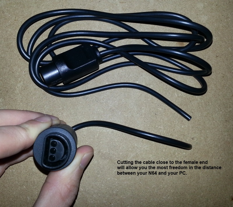
- First you will need to cut your controller extension cable so you can splice into the wires (consider which spot in the extension cable to cut, game system side, controller side, middle)
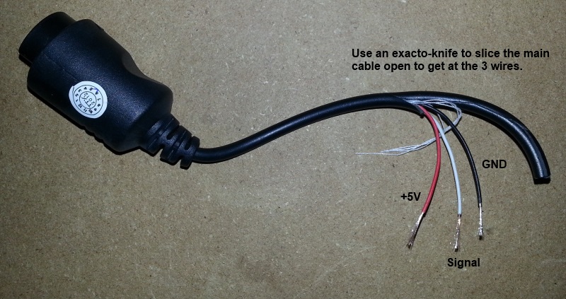
- Use your exacto knife or box cutters to very carefully cut away and peel back the plastic covering on both halves, about 2-3 inches should be good enough.
- Use wire strippers to strip back about 1/2 an inch of the plastic covering on each wire. In my case I had to carefully use my exacto knife because the wires were too small for the stripper, I rotated the wire against the blade until I could pull the plastic off the end.
- Next you will need to use a digital multimeter or continuity tester to figure out which pin on your controller plugin goes to which wire in the extension cable, make sure to write down your findings. Do NOT trust the color of the wires, the colors will vary from cable to cable.
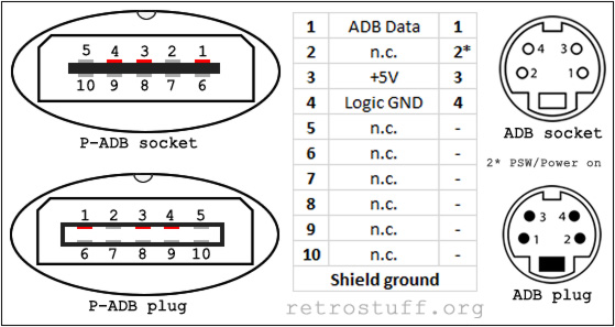
- For the Pippin you need to splice the ADB Data (pin 1), GND (pin 4) based on this pinout.
- Figure out the length you need between your controller extension cable/Arduino and cut and strip a wire for each wire you are going to splice into.
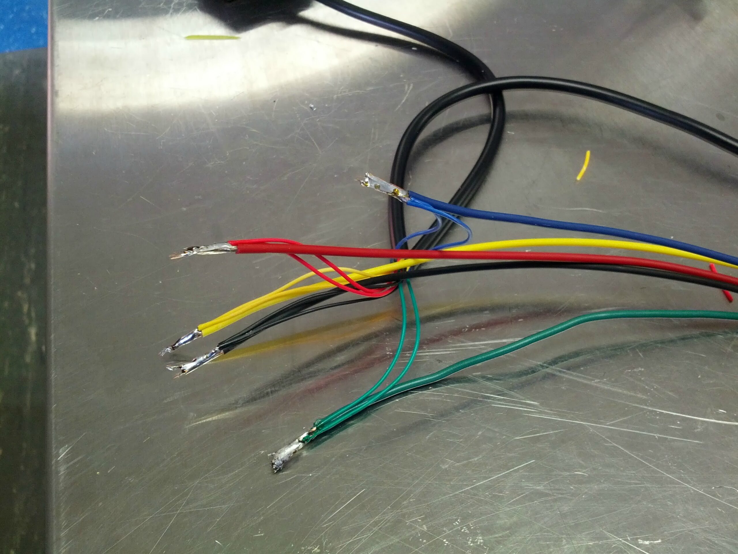
- Solder each wire back together with your spliced wires, here’s what mine looked like when finished I soldered them this way (instead of end-to-end) because this will provide more strain relief against the small controller extension wires possibly breaking with use.
- After soldering everything back together, test out your extension cable with your game system to see that it still works before proceeding.
- Use electrical tape to tape up each wire separately.
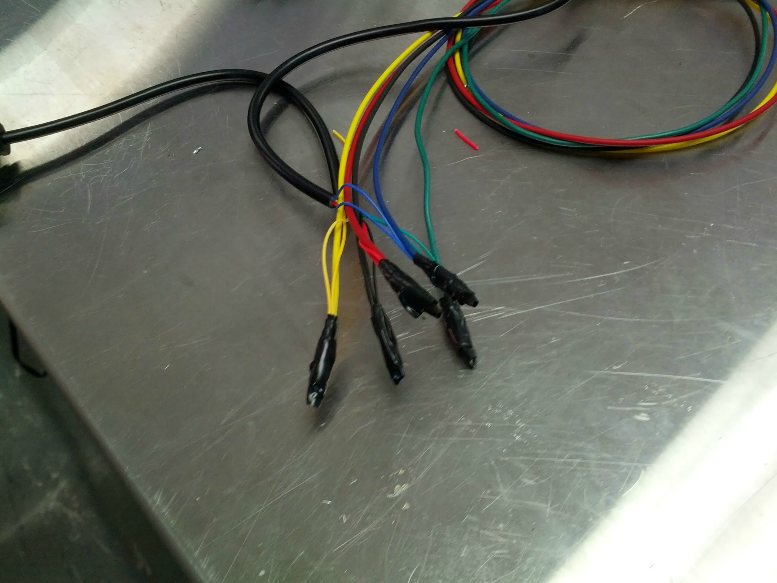
- Again use electrical tape to tape all the wires back together, make sure to tape all the way back up to where the extension cable covering starts.
Hooking it up
- Download and install the latest release of RetroSpy.
- Install the latest Arduino software, download the Windows Installer option. If you are not programming your own board you can skip this step.
- Hook up the RetroSpy cable to your Arduino according to this pinout.
Pippin Pin Arduino Digital Pin 1 (ADB Data) 2 2 Not Connected 3 Not Connected 4 (GND) GND 5 Not Connected 6 Not Connected 7 Not Connected 8 Not Connected 9 Not Connected 10 Not Connected - Plug the controller into the RetroSpy cable.
- Plug the RetroSpy cable into the Pippin.
- Plug the USB cable into the Arduino.
- Plug the other end of the USB cable into the display PC.
Program the Arduino
If you purchased a pre-programmed board, skip this section and continue to the RetroSpy application setup.
- Install the Arduino IDE and connect the Arduino to the computer.
- Open
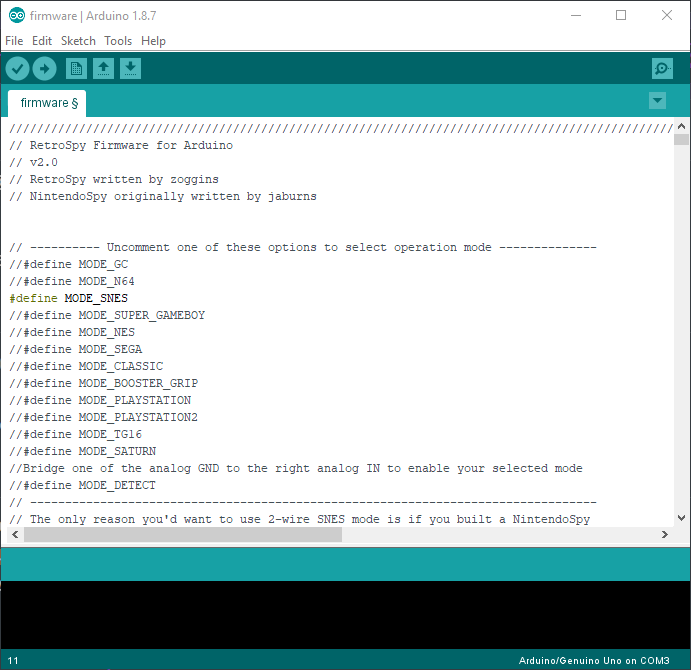
firmware/firmware.inofrom the latest RetroSpy release. - In the firmware options, enable
MODE_PIPPIN. Leave only the mode required by this guide enabled. - Select the correct board and serial port in the Arduino IDE.
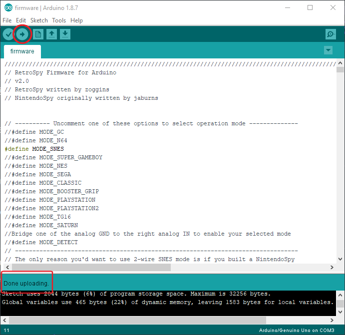
- Choose Upload. Wait for the IDE to report that the upload completed successfully.
Use the RetroSpy application
- Connect the programmed board and power on the console or controller adapter.
- Launch the RetroSpy desktop application from the latest release.
- Select the serial port used by the board.
- Select Pippin on Arduino Getting Started and choose a skin.
- Choose Go, then press controller buttons to confirm that the display responds.
Troubleshooting
- No serial port appears
- Reconnect the USB cable, try a data-capable cable or another USB port, and restart the application.
- The display opens but inputs are wrong
- Confirm the selected controller type, firmware mode, and every pin connection.
- The controller stops working on the console
- Disconnect the RetroSpy board and retest the extension cable. Look for a short, reversed connector, or damaged splice.
- Still stuck?
- Contact RetroSpy support and include the console, controller, board type, firmware mode, and a clear wiring photo.