This is considered an advanced setup because it requires the programming of two Arduinos and has a calibration step.
What You Need
- Two of the following boards:
- Arduino Uno
- Arduino Nano
- Pre-programmed Arduino Uno from the RetroSpy store
- USB cable(s) to connect the Arduino to your computer
- A RetroSpy AmigaAnalog cable for each board, if two boards are required. Do one of the following:
- Buy a pre-made cable from the RetroSpy store
- Make you own using the instructions under Wiring – No Soldering Required
- Atari/Genesis Controller extension cable
- DB9 Male Breakout Board to Screw Terminals
- DB9 Male to 2 Female Splitter
- Wires connect to the breakout board, like these
- Make you own using the instructions under Wiring – Soldering Required
- Atari/Genesis Controller extension cable
- Wires to solder into the controller extension cable to go to the Arduino, like these
- Wire cutters/strippers
- Soldering iron and solder
- Electrical tape and/or heat shrink tubing
- Digital multimeter or a cheap continuity tester
Software
- The latest Arduino software
- Firmware for the Arduino
- PC software to connect to the Arduino and display the controller
#2 and #3 above are included in the release package of RetroSpy. The firmware is located in the firmware folder and is called firmware.ino. Just run RetroSpy.exe to launch the display software.
Instructions
Wiring – No Soldering Required
It is possible to solder jumper wires onto each wire of the extension cable like some other platforms, but since the we are dealing with a standard port type, we can build a cable with no soldering required.
- Take the extension cable, wires, Breakout Board and Y cable you have acquired and put them together in this configuration:

Wiring – Soldering Required
This is the most time consuming piece, especially if you have never done any wiring/soldering before.
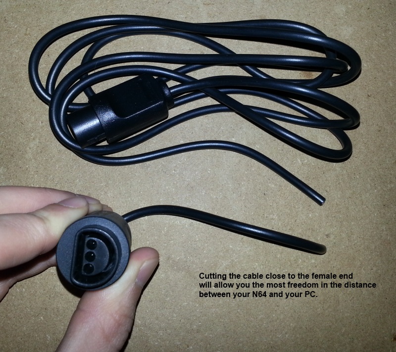
- First you will need to cut your controller extension cable so you can splice into the wires (consider which spot in the extension cable to cut, game system side, controller side, middle)
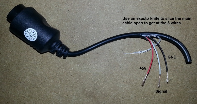
- Use your exacto knife or box cutters to very carefully cut away and peel back the plastic covering on both halves, about 2-3 inches should be good enough.
- Use wire strippers to strip back about 1/2 an inch of the plastic covering on each wire. In my case I had to carefully use my exacto knife because the wires were too small for the stripper, I rotated the wire against the blade until I could pull the plastic off the end.
- Next you will need to use a digital multimeter or continuity tester to figure out which pin on your controller plugin goes to which wire in the extension cable, make sure to write down your findings. Do NOT trust the color of the wires, the colors will vary from cable to cable.
- If you are just using the cable for Atari-style controllers you need to splice every pin, but 7. However if you want to use this cable for other DB9-based consoles you will want to splice all 9 pins.
- Figure out the length you need between your controller extension cable/Arduino and cut and strip a wire for each wire you are going to splice into.
- Solder each wire back together with your spliced wires, here’s what mine looked like when finished I soldered them this way (instead of end-to-end) because this will provide more strain relief against the small controller extension wires possibly breaking with use.

- After soldering everything back together, test out your extension cable with your game system to see that it still works before proceeding.
- Use electrical tape to tape up each wire separately.

- Again use electrical tape to tape all the wires back together, make sure to tape all the way back up to where the extension cable covering starts.
Hooking it up
- Download and install the latest release of RetroSpy.
- Install the latest Arduino software, download the Windows Installer option. If you are not programming your own board you can skip this step.
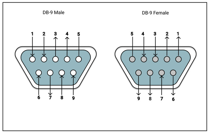
- Hook up the RetroSpy cable to your Arduino according to this pinout.
DB9 Pin Arduino 1 Pin Arduino 2 Pin 1 Digital 2 Not Connected 2 Digital 3 Not Connected 3 Digital 4 Not Connected 4 Digital 5 Not Connected 5 Analog 0 Not Connected 6 Not Connected Not Connected 7 Not Connected Not Connected 8 GND GND 9 Not Connected Analog 0 Digital 12 Digital 12 - Plug the controller into the RetroSpy cable.
- Plug the RetroSpy cable into the Amiga.
- Plug the USB cable into the Arduino.
- Plug the other end of the USB cable into the display PC.
Software Setup
Once the wiring is done and everything is hooked up to your game system and computer, now for the easy part.
- Make sure the the USB cable between your Arduino and PC is connected and if you are not going to program your own board you can now skip to Step 10.
- Open the Arduino software that you installed above.
- Once installed, open the Arduino software, you should see “Arduino Uno on COMX” at the bottom right corner if everything is working. If not, you may need to restart and/or replug the USB connector. Make sure COMX is your the Arduino wired up as your 1st Arduino.
![]()
- Open common.h in the RetroSpy installation directory (by default this is
C:\Program Files (x86)\RetroSpy\firmware) with any available text editor and uncomment the line//#defineAMIGA_ANALOG_ADC_INT_HANDLER. - In the Arduino software select File->Open from the menubar and open the
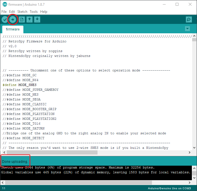
firmware.inofile from the firmware folder of the installed RetroSpy release (by default this isC:\Program Files (x86)\RetroSpy\firmware). - Now uncomment the option for
MODE_AMIGA_ANALOG_1. Note thatMODE_SNESis uncommented in this image.
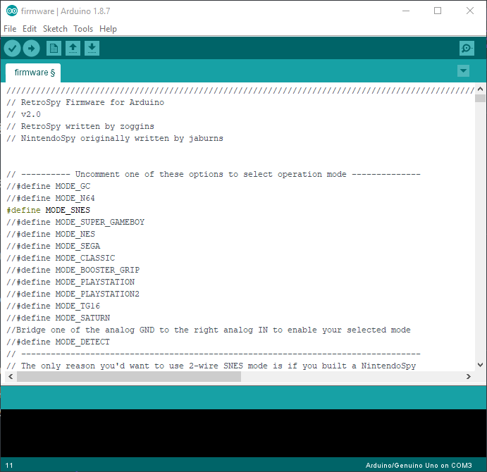
- Hit the upload button (right pointing arrow) located just under the ‘Edit’ menu, this will upload and run the software on the Arduino. It should look like the following image. Once successfully uploaded, you won’t have to upload software again to the Arduino again unless you want to change controller modes.
- Now select your 2nd Arduino in the Arduino IDE the
Tools->Portmenu. Recomment outMODE_AMIGA_ANALOG_1and then uncomment outMODE_AMIGA_ANALOG_2fromfirmware.ino. Repeat Step 8. - Power on your console.
- Run
RetroSpy.exe. - The selection here should be pretty straightforward, select the ‘COMX’ port that the Arduino is on, select the controller you are using, select a skin, and hit ‘Go’. If everything is hooked up correctly you should see your controller and inputs displaying.
- If you didn’t press any buttons on the joystick you should see the display of the joystick moving erratically. This means the joystick is ready to be calibrated. If you accidently pushed a joystick button to enter calibration reset Arduino 1, wait 10 seconds and reset Arduino 2. To calibrate simply move the joystick is full range of motion in every direction until the display settles down into what you expect it should look like. Once everything looks good, push any joystick button to lock the calibration. This calibration only needs to be done when you power up the Arduinos, it persists across console restarts. If you ever need to recalibration simply reset Arduino 1, wait 10 seconds and reset Arduino 2.
Recent Comments